Universal Tacho Circuit Board Replacement |
|||||||||||||||||||||||||||||||||||||||||||||||||||||||||||||||||||||||||||||||||
| << back |
|
||||||||||||||||||||||||||||||||||||||||||||||||||||||||||||||||||||||||||||||||
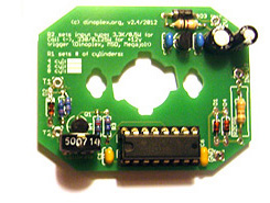
Introduction The circuit described here is a replacement for the electronic board installed in vintage electronic Veglia and Smiths tacho's. If your tacho is broken because of a board defect then it can be a more economic approach to exchange the circuit board instead of trying a repair. This is usually the case with early tacho's using out of production germanium transistors and later Veglia tacho's which use integrated tacho driver ICs such as the SN29736P or the 14 pin version of the SL494, as both ICs are difficult to source nowadays.You can use this circuit board to Features and Specifications Files for downloading Circuit Diagram The circuit is based on the industry standard CD14538 chip, which features two independent precision monostable multivibrators (IC1A and IC1B). The second monostable multivibrator is not used so the input pins are wired to ground. 'IC1P' are the two power supply pins on the CD14538 chip (GND/VSS: pin 8 and VCC/VDD: pin 16). 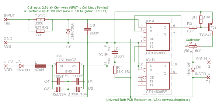 Circuit Board Assembly Components Here is the list of the required components:
1. Tacho Type Configuration Adapting the circuit to different tacho types/manufacturers only requires changing R1, which controls the output signals pulse width:
R2TRIG Resistor In general, a dedicated tach out signal is preferred as input over a coil connection if both are available. Never use a direct coil connection with a CDI ignition as this can damage the tach circuit and will lead to erroneous readings with multiple spark discharge ignitions such as the MSD 6A. 3. Cylinder Configuration The calibration range of the standard circuit with a 500Ω trimmer (R5) should be sufficient to calibrate a tach for either a four, six or eight cylinder engines if R1 is properly set. 4. Assembly Use one of the Eagle CAD board design files from the download links above to have a layouted PCB created, or simply solder everything to a prototype board. Below are some examples of assembled tacho circuit boards. Veglia tacho's use the following wire colors: blue for ground, red for +12V and yellow for trigger in. 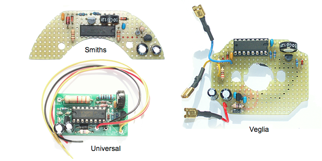 For the installation, check which of the two small wires going from the old circuit board to the instrument coil terminals (behind the dial face) is the positive wire. Connect T1 on the new circuit board to the coil terminal where the positive wire was installed, and T2 to the other instrument coil terminal. On older Veglia tachs where the original PCB board had two transistors, the positive terminal is at the six o'clock position (lower terminal) as seen from the front. Newer Veglia tachs using an IC instead of transistors on the PCB have the positive terminal on the twelve o'clock position (upper terminal). On Smiths tachs, the positive terminal is on the right side as seen from the front. 5. Calibration The tacho calibration is handled via the trimmer R5. Set the trimmer to a middle position before you start the calibration. For the calibration it is recommended to have access to a square wave generator, which can generate frequencies between 10-500 Hz and has a variable output amplitude up to 12 Volts. You can also calibrate the tacho while it is installed in the car by comparing the readout of a digital strobe gun or RPM counter and then set the tacho accordingly, but it is much more comfortable and more precise to do this with a square wave generator. Calibrate the tach for the RPM which is displayed at the twelve o'clock position of the dial for best results. Here is the conversion from RPM to HZ for setting the square wave generator output frequency: Example, when the RPM value indicated at the twelve o'clock position of your tacho is 4000 for a six cylinder engine, set the frequency generator to 200 HZ (4000/20). Now adjust the tacho by varying trimmer R5 until the tacho needle is in line with the RPM value you set on the square wave generator. With a mechanically good tacho you should be able to get a display error of 5% or less. Examples Top left: '69 Veglia tach (Fiat Dino), top right: '68 four cylinder Smiths RVI tach, lower left: '78 Veglia tach (Ferrari 308 GTB), lower right: '72 Datsun tach (Datsun 240Z). 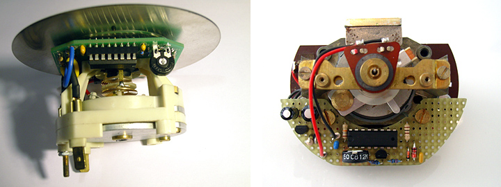 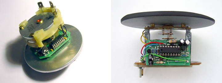 Appendix: Troubleshooting If the needle does not move when testing the assembled tacho, check that T1 (+) and T2 (-) are wired to the corresponding terminals on the instrument coil, and that the input signal matches the input configuration (R2TRIG or R2COIL). Also check that IC1 receives 8V supply voltage on pin 16.If you don't see 8V, check the input and output pins of the 7808 voltage regulator. Below are two scope screenshot of the input signals at different stages for easy diagnosis: 1: Electronic Tach input Signal 2: Input signal after Zener Diode/input filtering 3: Q1 Base, coming from CD14538BE (pin 6) 4: Output signal (shown inverted), driving a Veglia tacho 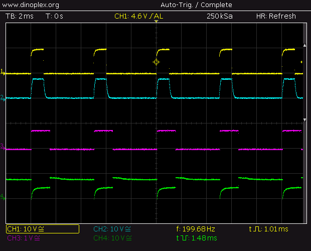 1: Coil (-) terminal (Coil and Points setup) 2: Input signal after Zener Diode/input filtering 3: Q1 Base, coming from CD14538BE (pin 6) 4: Output signal (shown inverted), driving a Veglia tacho 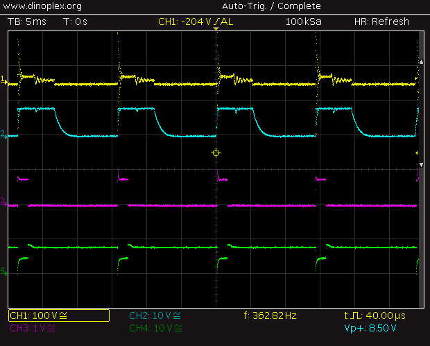 |
|||||||||||||||||||||||||||||||||||||||||||||||||||||||||||||||||||||||||||||||||