| |
Quick repair for the impatient
The most common defect is a failure of one or both of the power transistors T1 and T2, which are part of
the inverter circuit. If your Dinoplex unit does not emit a humming high pitched sound after applying power
to the unit in the "Normale" setting and there is no current measurable going through 'B+' (the +12V supply
wire of the Dinoplex, which is connected to the coil B+ terminal), then exchange both transistor T1 and T2
against a new pair of 2N3773. Don't forget to apply thermal grease between the back of the transistor and
the ceramic plate, and between the ceramic plate and the Dinoplex enclosure. Also exchange capacitor C2 (150uF/63V) as it is most probably gone by
now.
Principle of Operation
The Dinoplex AEC101C is a so called capacitive ignition, it creates a high voltage (500-600 V DC) using an
inverter circuit (T1, T2, transformer) and rectifier (D1-D4), which is then used to charge a large capacitor (C4). With each
ignition trigger, the capacitor is discharged via an electronic switch (thyristor, THR1) into the BZR205A
ignition coil. The ignition coil then acts as a step-up transformer to create a high voltage output impulse
of about 40-45 KV.
Humming Sound
A humming sound is normal and indicates that the inverter of the Dinoplex is functional. The sound you can
hear is the vibration of the transformer core at 240-280Hz. The pitch can change slightly depending on the
input voltage. A very high pitched sound indicates a defect of one of the two inverter transistors (T1/T2).
Diagnosis and Repair
|
|
| 1. No humming sound with ignition on
and Dinoplex switch set to "Normale", unit draws no current |
- Check that the unit is properly grounded
- Make sure that the unit receives power by checking for ~12.5V on terminal 7 of the transformer
(lower left terminal, check for a red wire). If the unit has a large 'Normale/Emergenza' switch, it
must be set to 'Normale'. If you don't see ~12.5V on units with a switch, disassemble the switch
and check/clean the contacts.
- If the unit receives ~12.5V and is properly grounded, test T1 and T2 (2N3773) by removing the
transistor leads and measure the hFE value of the transistors. You should see a value of at least
40 hFe for each. Replace both if broken or hFe value below 40. Apply thermal grease between the back of the transistor and
the ceramic plate, and between the ceramic plate and the Dinoplex enclosure.
- if the unit still does not work after the transistor exchange, check the wires and solder
joints coming from transformer terminal 13 and going to R2 and from transformer terminal 16 going
to R1
- If you can measure a primary current but have no humming sound yet, continue with step 2
|
| 2. Low crackling or no sound and input
current higher than 2.4 ampere |
- Remove power from Dinoplex at once to avoid transformer damage
- Open Dinoplex and desolder the wire connected to PCB solder point 'A'. Do not touch wire or
Dinoplex when power is applied, terminal A/B will carry >500V!
- Apply power, if you can hear the standard humming sound now, remove power again, and check the rectifier diodes (D1-D4). If they are broken, replace them. If the rectifier is ok though, replace
thyristor THR1 (C137PB) against a new one and reconnect wire to solder point 'A'. Also check D5
while you exchange THR1.
- If there is no humming sound after removing the wire from solder point 'A', then one or both of the power transistors (T1/T2) are broken, replace both and retest.
|
| 3. Humming sound can be heard but no
sparks are generated |
- This can be an indicator for a defective coil. Make sure to first check the coil or try a known to be good one before you start swapping parts in your Dinoplex
- Check the distributor points to make sure it properly grounds and opens the connection, also
check the points wire going to the coil resistor terminal 'D'
- If the points and wiring is ok, check the PCB for cold solder joints at C1, R6, D8, R9 and
D7. If all joints are ok, check and replace D7 if broken.
- If this did not fix the issue, test thyristor THR1 (C137PB) and replace if broken. Also check
D5.
- Measure the capacity of the large cylindrical capacitor C4, you should see 1.2-1.4uF. If the
capacitor is below 1.2uF, exchange against a new one
- Measure the AC voltage across solder point 'A' and 'B' using a multimeter or scope capable of
handling at least 600-800 Volts AC. You should see 540-580 Volts AC. If you see less, check the
hFE value of T1 and T2 and replace both if necessary. (Apply thermal grease between the back of the transistor and
the ceramic plate, and between the ceramic plate and the Dinoplex enclosure).
|
4. Humming sound can be heard but
engine does not rev above 3000-4000 RPM and/or backfiring occurs
|
- Apply tests in step 3.: start by measuring C4, then check the thyristor
- If this does not fix the issue, apply all other tests from step 3
|
| 5. Humming sound can be heard and
engine runs normal when cold but misses and hesitates when hot |
- Make sure there are no issues with the carbs, fuel pump or vapor locks
- Check the coils LCR values as described below with the coil at room temperature and being
warm, there should be no difference in the values
- Carefully check the PCB for cold solder joints and resolder where necessary
- Check the transformers condition as described below
- Replace T1/T2 (apply thermal grease between the back of the transistor and
the ceramic plate, and between the ceramic plate and the Dinoplex enclosure), if this did not fix the issue, also replace THR1
- Continue with step 6. if the problems still persist.
|
| 6. Humming sound varies in frequency, ignition sometimes stops to work at all |
- Check the solder points for the wires going to R1 and R2, resolder if necessary
- If the humming sound still varies, replace R1 and R2
- If this did not fix the problem, open the Normale/Emergenza switch and check the contacts for the +12V supply, clean them if necessary
|
| 7. Very high pitched humming sound |
- Check the hFE value of T1 and T2 and replace both if one is broken. (Apply thermal grease between the back of the transistor and the ceramic plate, and between the ceramic plate and the Dinoplex enclosure).
|
|
| |
Transformer Health Test
The insulation varnish used by the factory to isolate the transformers primary and secondary windings will
get very brittle over time and then start to crumble, leading to shorts in the transformer coil windings. The
actual damage to the wiring insulation depends upon the usage, heat and vibrations the Dinoplex encountered
in its service life. The following tests help to figure out the condition of the transformer if the Dinoplex
itself is ok and working (e.g. no T1/T2 or THR1 defects).
Make sure that your cars battery is fully charged and has a voltage of 12.5V. Connect a multimeter capable of
measuring up to 10A to the B+ wire or use a current clamp on B+. Switch on the ignition (but don't start the
engine) and measure the idle current of the Dinoplex.
- 1.6-1.7 A: Excellent, rarely used, condition as delivered by the
factory
- 1.8-1.9 A: Typical current value for a lightly used Dinoplex, unit is in good
health
- 2.0-2.2 A: Normally used Dinoplex, transformer windings have some light
damage
- 2.2-2.4 A: Very used Dinoplex, windings are partially damaged, might work for
some more years
- >2.4 A: Heavily used Dinoplex, windings have critical damage, recommended to
exchange transformer
|
| |
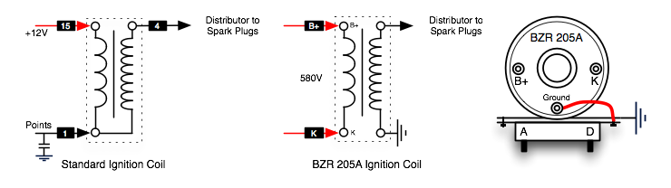
BZR205A Coil Diagnosis
The BZR205A coil for the Dinoplex C is different from a standard coil, as it has a separate ground
terminal for the secondary winding. The primary winding of the BZR205A is not connected to ground. Standard coils
have a common ground for the primary and secondary winding. Unfortunately it is not possible to use
a standard (two terminal coil) as a replacement, as with a standard two terminal coil the secondary spark voltage will have no direct ground connection and so will either go back via the Dinoplex or damage the secondary wiring insulation to discharge through the (grounded) coil body.
1. Using a multimeter in resistance measurement mode, the primary
side (terminal 'B+' and 'K') should have a resistance of around 1.6Ω-1.8Ω
(Ohm), the secondary side (king wire connector, middle screw terminal) around
6.0KΩ-6.5KΩ +-10%.
2. A resistance test with a multimeter will just show you if the coil is really broken though, to find
out about partial defects such as wiring shorts inside the coil's wiring you need to use a good
quality LCR Meter, which measures the inductance and resistance using a frequency signal:
Set the LCR meter to a 1 KHz test signal and connect the test leads to the primary side (terminal
'B+' and 'K'):
- Set the LCR meter to inductance mode, you should see around 5.6-5.8 mH
(milliHenry)
- Set the LCR meter to resistance mode, you should see around
210Ω-230Ω (Ohm)
Connect the test leads to the secondary side (king wire connector, middle screw
terminal):
-
- Set the LCR meter to inductance mode, you should see around 42-48H
(Henry)
- Set the LCR meter to resistance mode, you should see around
1.8KΩ-2.0KΩ (KiloOhm)
A variance of more than +-20% of a measurement compared to the values above usually indicates a
defective coil.
If you can't get hold of a replacement BZR205A coil, you could use a Marelli BAE 202B coil as replacement instead. For this replacement you need to add a single one ohm (1Ω) resistor in line with the Marelli ballast resistor (connect the 1Ω resistor inbetween the 'A' (yellow ring) wire and the left terminal of the Marelli ballast resistor).
|